HexaFlow
A NASA HUNCH finalist nanolab: a 3D-printed hex dome that moves water to plant roots by capillary action. I led the website and its 3D viewer.
- SolidWorks
- SLA + FDM printing
- Raspberry Pi Zero 2W
- Astro
- Three.js
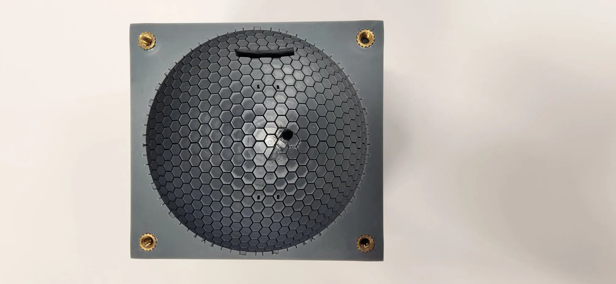
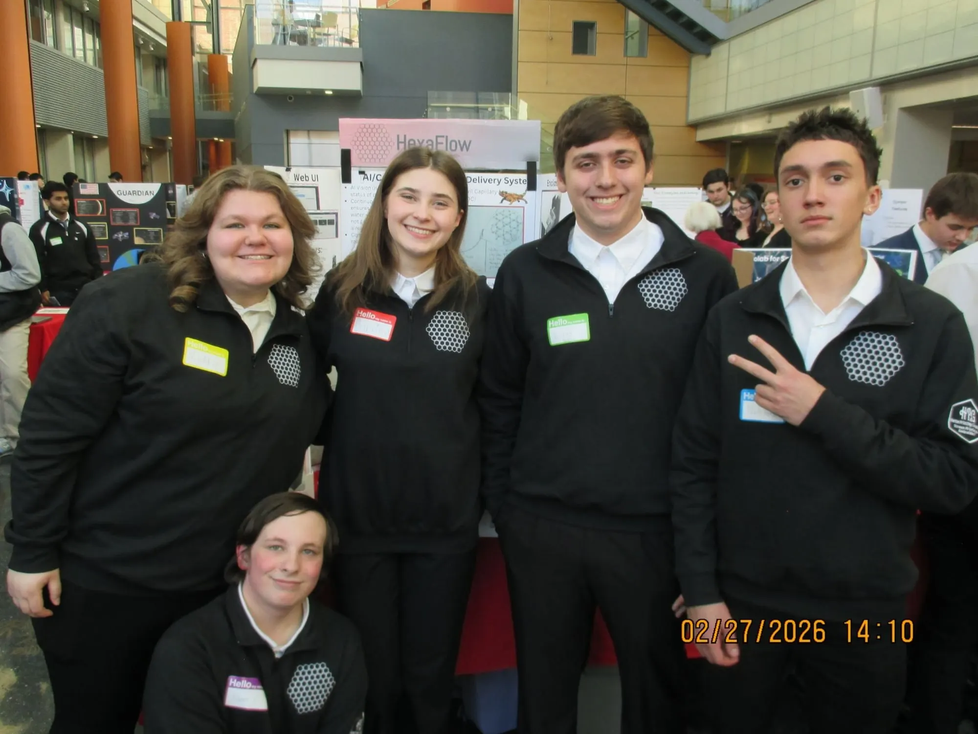
HexaFlow is a nanolab: a sealed box about the size of two stacked juice cartons that studies how water moves when there’s no gravity to pull it down. Five of us from Tri-County built it for NASA HUNCH, and it made the finals.
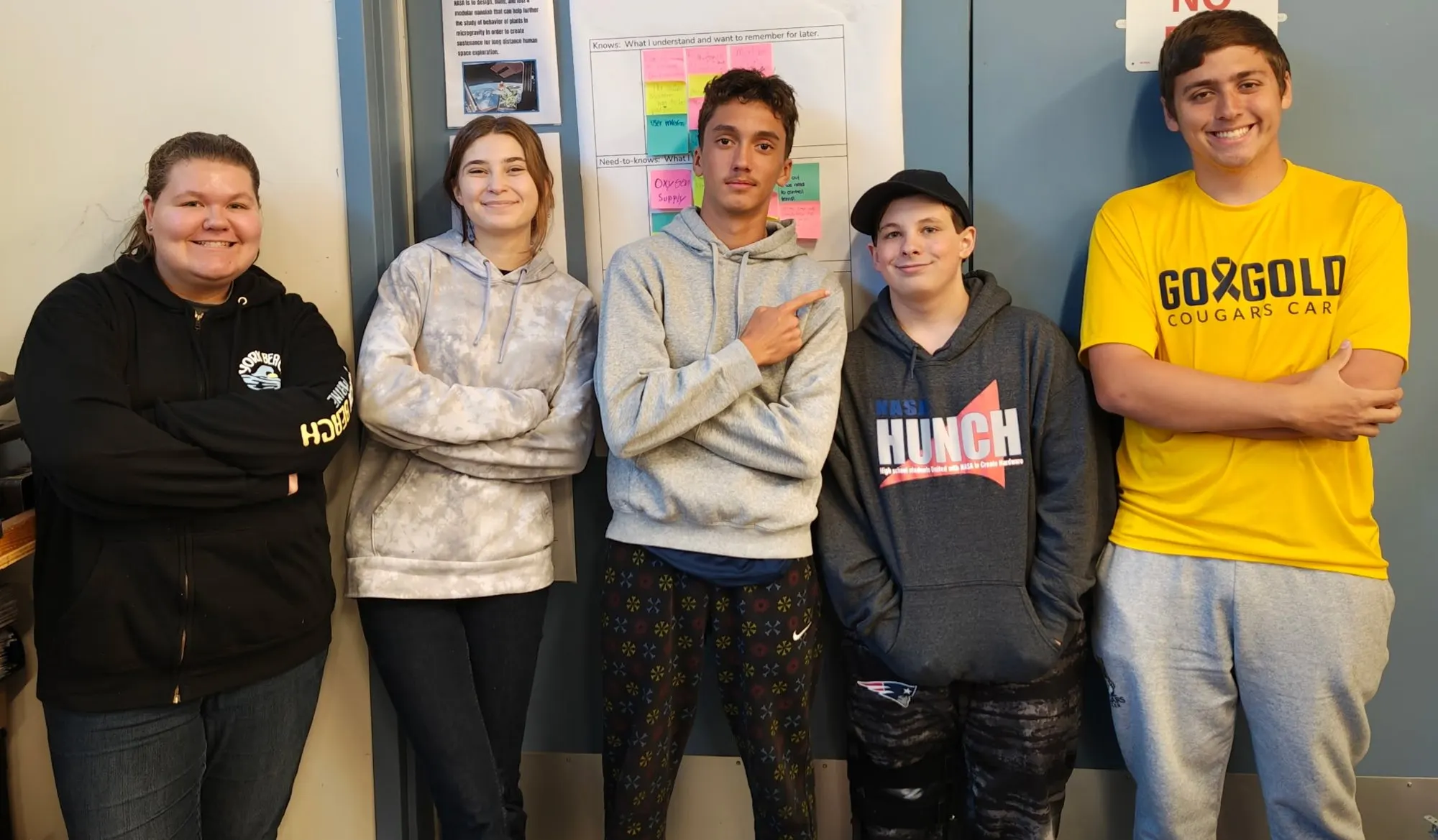
I was the web development lead. On a team of five you end up in everything, so this page covers the whole project, and the “My role” section says exactly which parts were mine.
The problem
HUNCH (High school students United with NASA to Create Hardware) gives high school teams real NASA problems with real constraints. There are design reviews with NASA reviewers, written documentation at every stage, and finalists present their work.
Our question was how water and plant substrates behave in microgravity. You need to understand that to feed people on long missions. The plant was the test subject. The water was the experiment.
On Earth, gravity waters a plant for you. Water falls through the soil and the roots pick it up. In orbit, water clings to whatever it touches and floats around in blobs. Pumps help, but they draw power, they fail, and a pump can’t tell where the water actually went.
NASA’s constraints for the box:
- 20 × 10 × 10 cm envelope (a 2U nanolab)
- 5 V, 500 mA of power over USB-A
- $100 total budget
- 50 mL maximum water on board
Condensation couldn’t reach the electronics, the parts had to be modular, and it needed a web interface. The experiment starts on a 24 V signal, so it has to run on its own from that moment.
The solution
A 3D-printed dome covered in hexagonal channels less than half a millimeter wide. Water injected at the center spreads through the channels by capillary action and reaches the roots of a plant sitting on top. No wicks, no soil, no gravity needed.
We didn’t start there. In September 2025 we read everything that came before us: NASA’s Veggie and the Advanced Plant Habitat, a 3D-printed substrate from the University of Michigan, older student payloads, and a few patents. The same gaps kept showing up: too big, not modular, water systems that needed power.
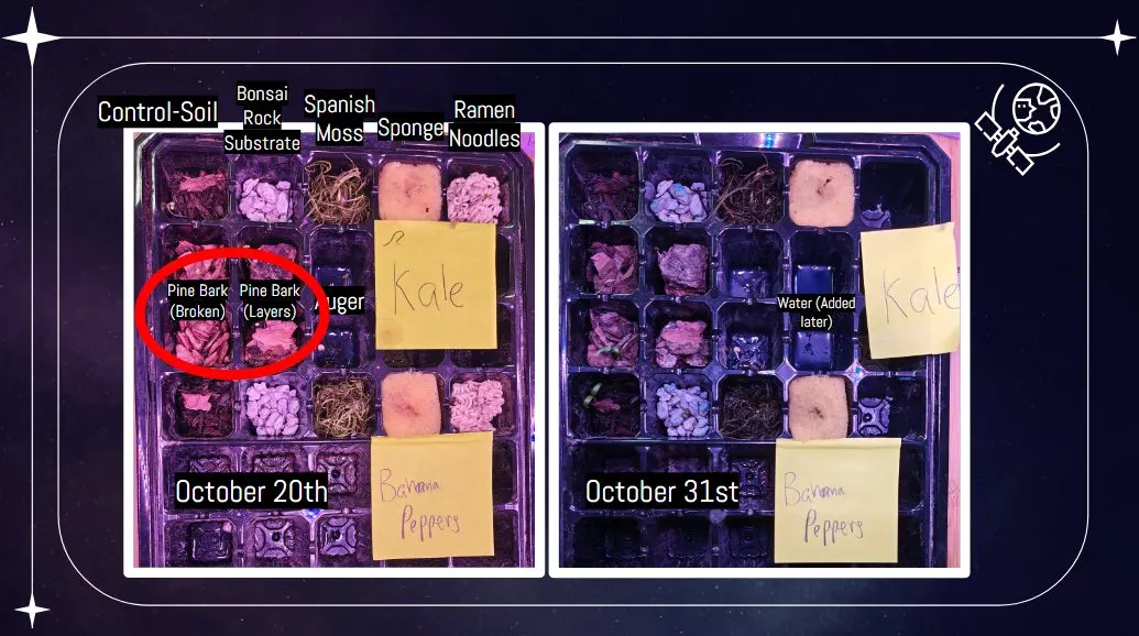
Our first idea was a growing substrate. We tested eight of them in October. Almost all of them grew mold. Only pine bark grew anything.
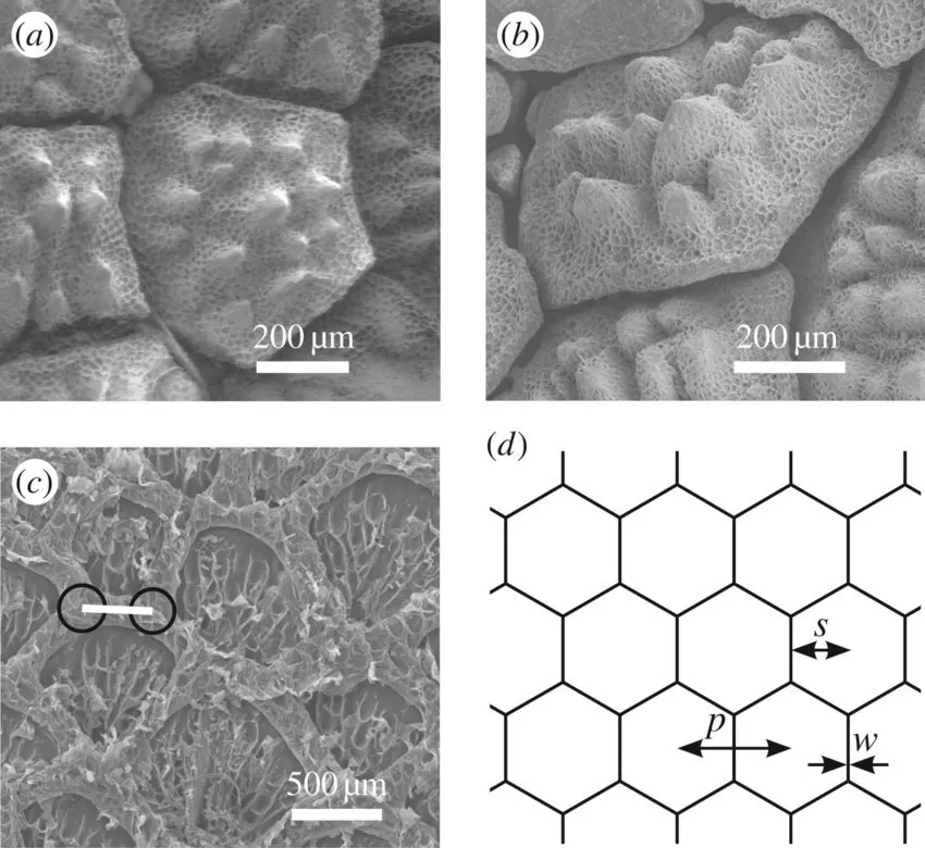
Hydroponics looked good until we realized it skipped the question we were supposed to study. Then on October 22, Sabrina found the thorny devil lizard on asknature.org. It lives in the Australian desert and drinks by touching damp sand. Tiny grooves between its scales carry water uphill to its mouth by capillary action. No pump, no muscles.
Nate modeled a first version in SolidWorks in two sizes, and it worked better than any of us expected. We named the core part the TDC, for Thorny-Devil Capillary.
How it works
Capillary flow
Capillary action happens when water sticks to a surface more strongly than it sticks to itself. In a narrow enough gap, the walls pull water along. That pull comes from adhesion and surface tension, not gravity. On Earth, gravity fights it. In microgravity, it’s the main force left.
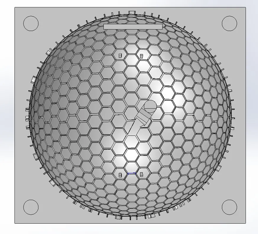
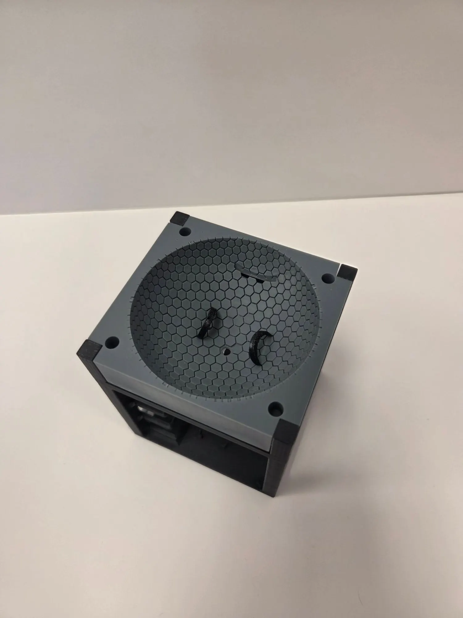
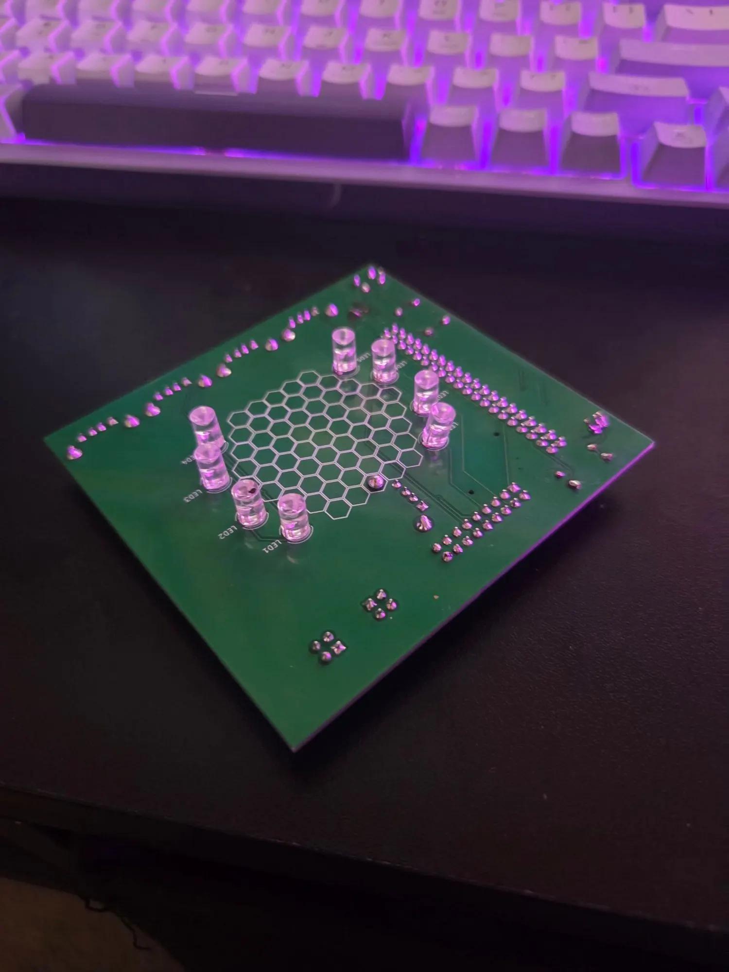
The TDC is a shallow dome covered in raised hexagons. The gaps between them are the channels. Water enters at the center, spreads outward through the lattice, and reaches the roots sitting directly in the channels.
Geometry and why
Channel size is a tradeoff. Wider channels hold more water but pull it weakly. Narrower ones pull hard but clog. Here’s where we landed:
| Feature | Size |
|---|---|
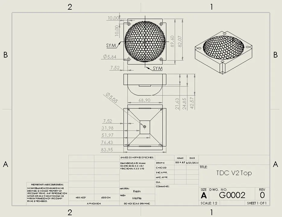
| Hexagon, side to side | 0.167 in (4.24 mm) |
| Hexagon side length | 0.100 in (2.54 mm) |
| Channel depth | 0.050 in (1.27 mm) |
| Gap between hexagons | 0.020 in |
| Channel width (measured) | 0.48 mm |
| Water the channels hold when full | 10.12 mL |
Material and why
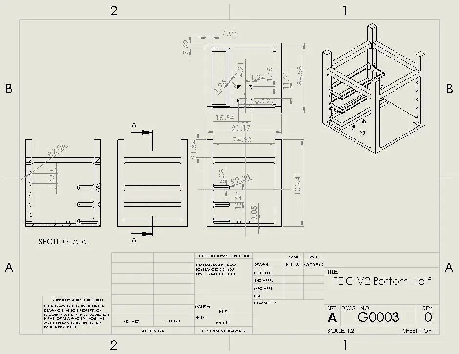
The dome is printed in resin on an SLA printer. Cured resin is polar, so water grips it more than it grips itself. That’s what drives the flow, and it’s why the dome holds water upside down. Only the dome is resin. The body underneath is FDM-printed PLA, which is cheaper and lighter.
What the design review changed
At our Preliminary Design Review in November 2025, NASA’s reviewer called the hexagon shape and the thorny devil idea “terrific.” The feedback was more useful:
- Point the camera at the water, not the plant. A drop test lasts seconds, so nothing grows during it. The data is in how the fluid moves.
- Dye the water so the camera can see it.
- Add one or two containment layers.
- Test at least two substrates.
Other teams warned us that wicking might not behave in microgravity the way it does on a bench. That objection shaped every test we ran after.
Enclosure
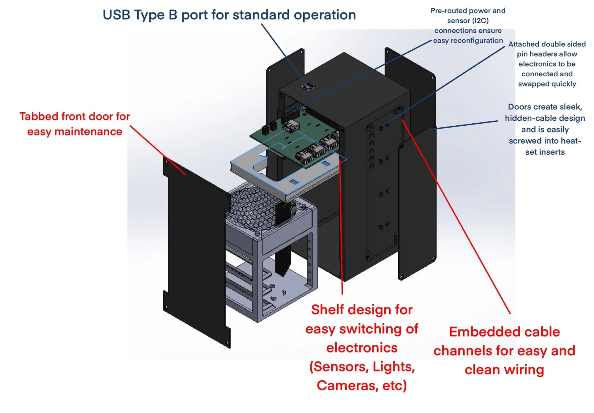
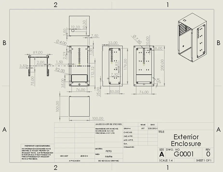
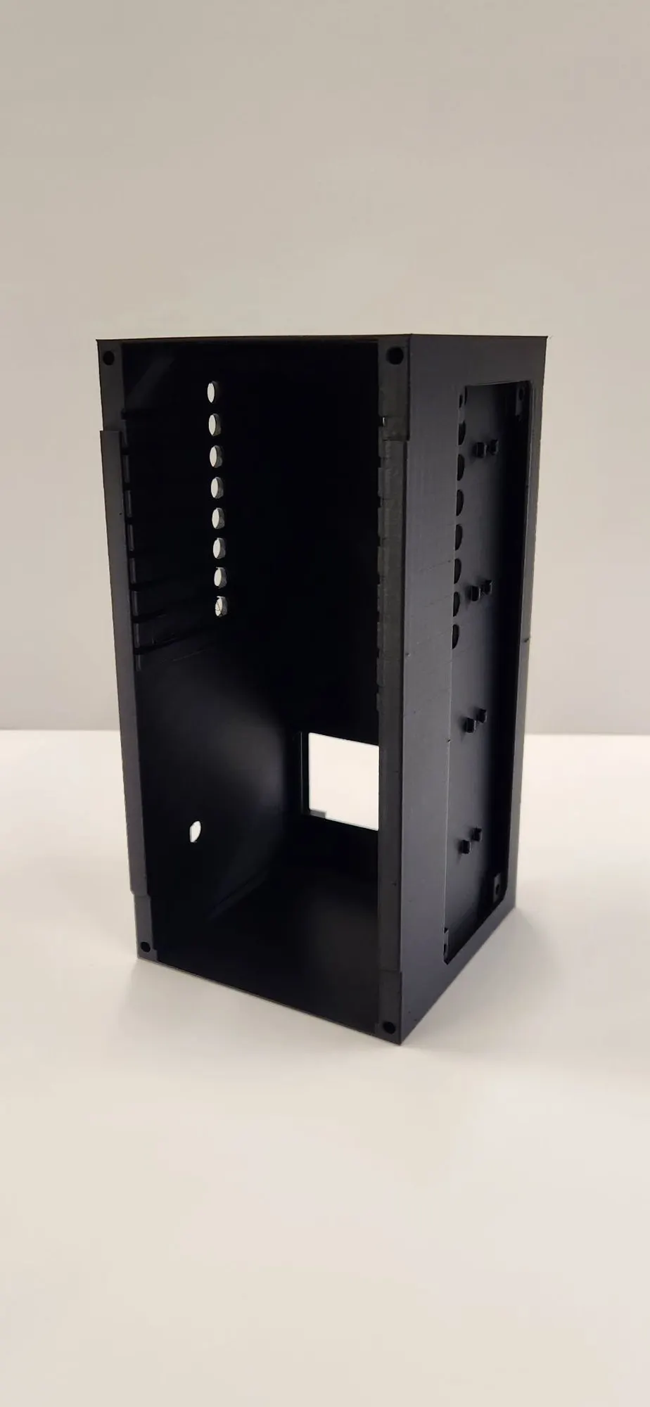
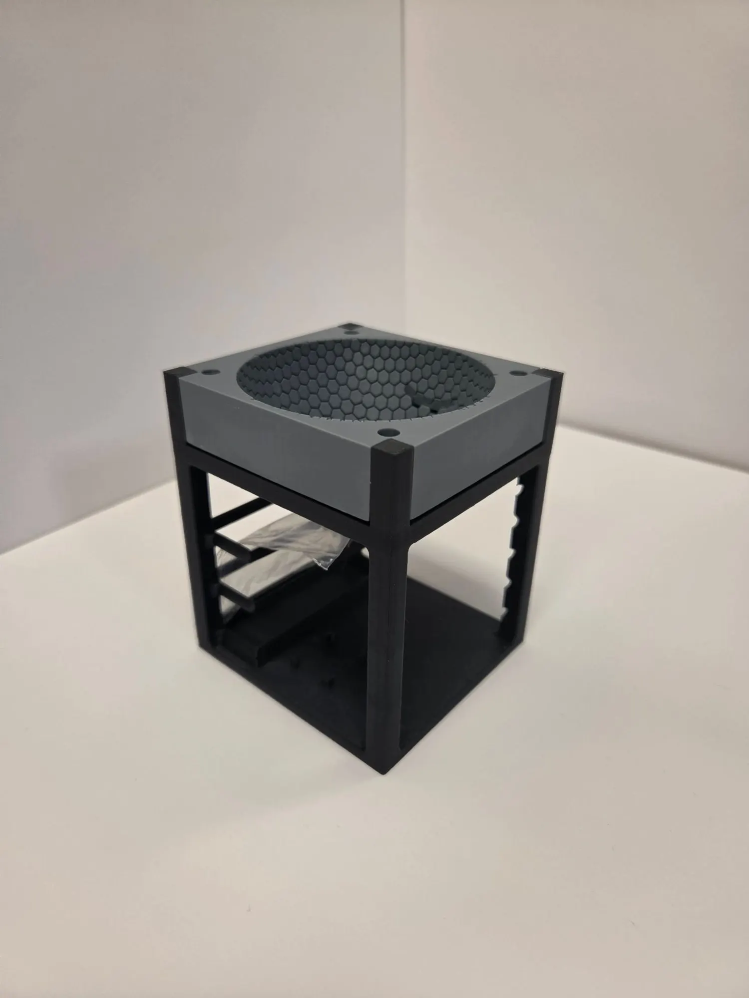
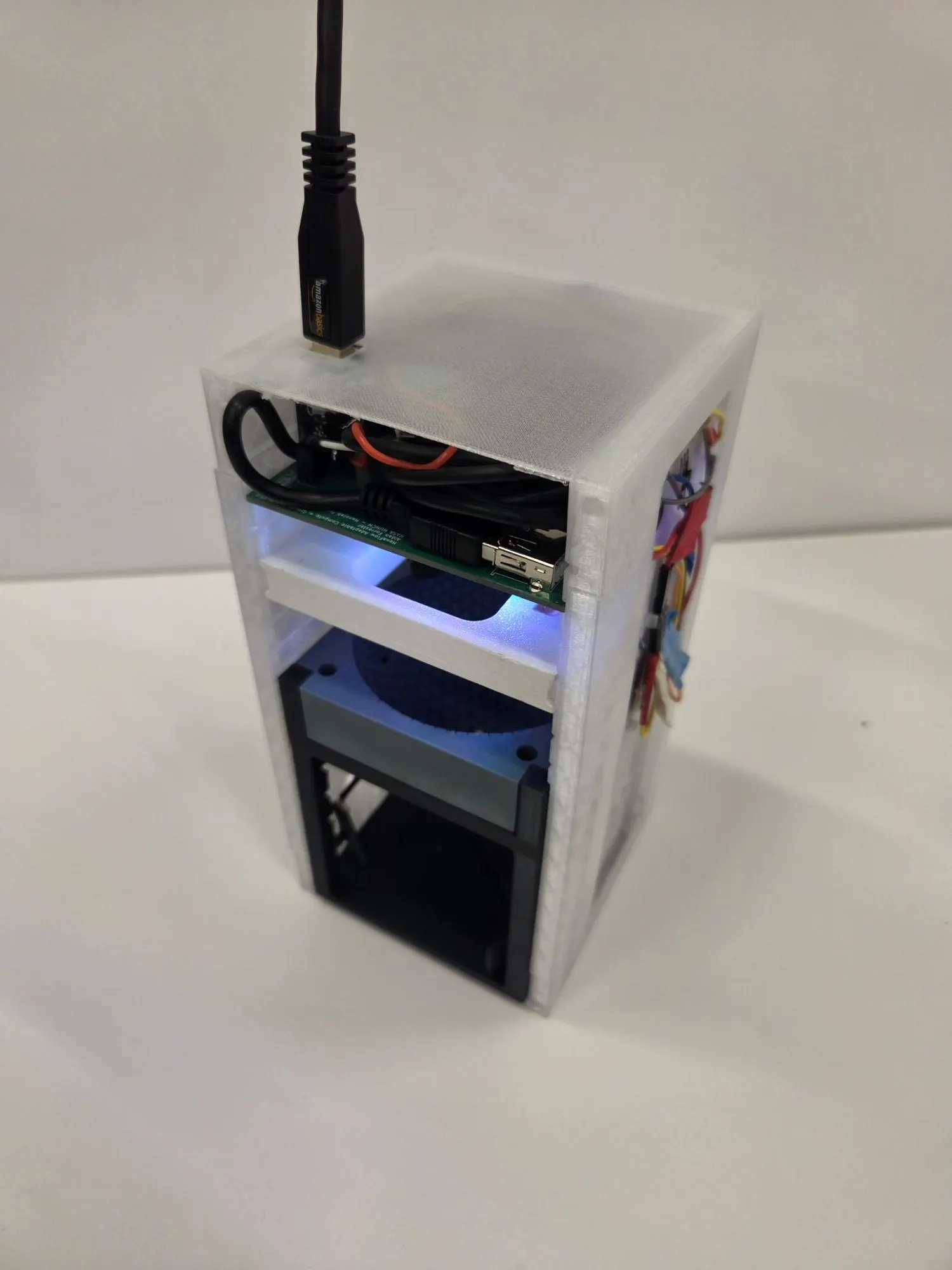
The enclosure went through seven versions between December and February. Each print showed us one more thing that didn’t fit:
- Wire holes went from 5 mm to 8 mm because the cables wouldn’t pass.
- Walls went from 4 mm to 2 mm to save weight and space.
- Half-slotted modules kept falling off their rails until we added supports.
- The reservoir became a heat-sealed pouch in a friction-fit pocket, so water could never sit next to the electronics.
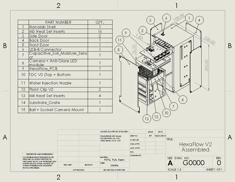
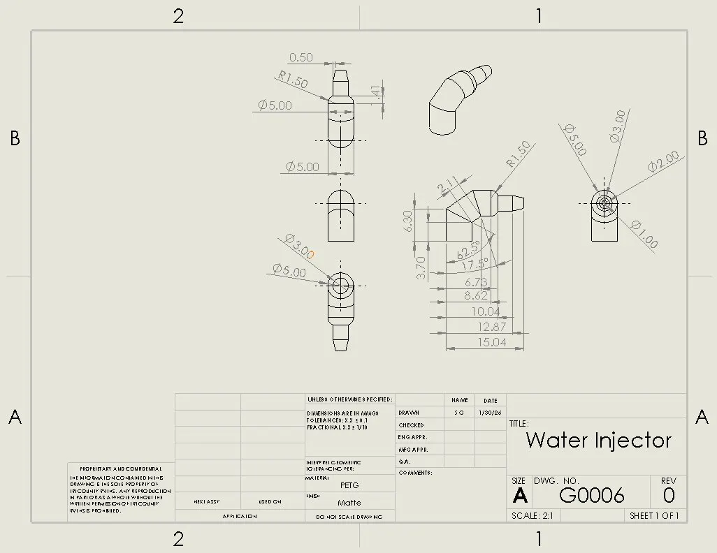
Version 2 has fifteen line items in its parts list, from the shell and doors down to the heat-set inserts. Every printed part has its own drawing.
Electronics
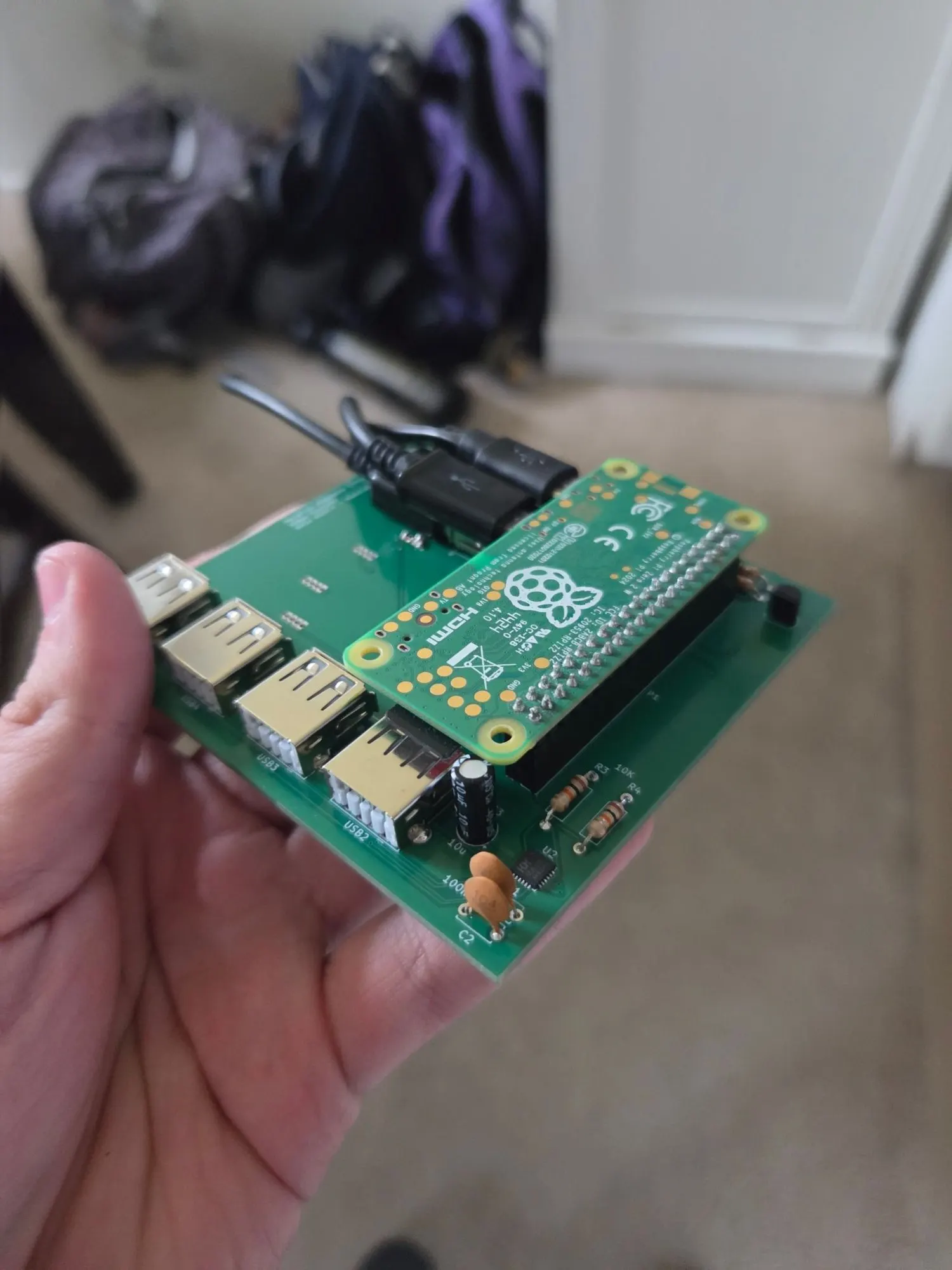
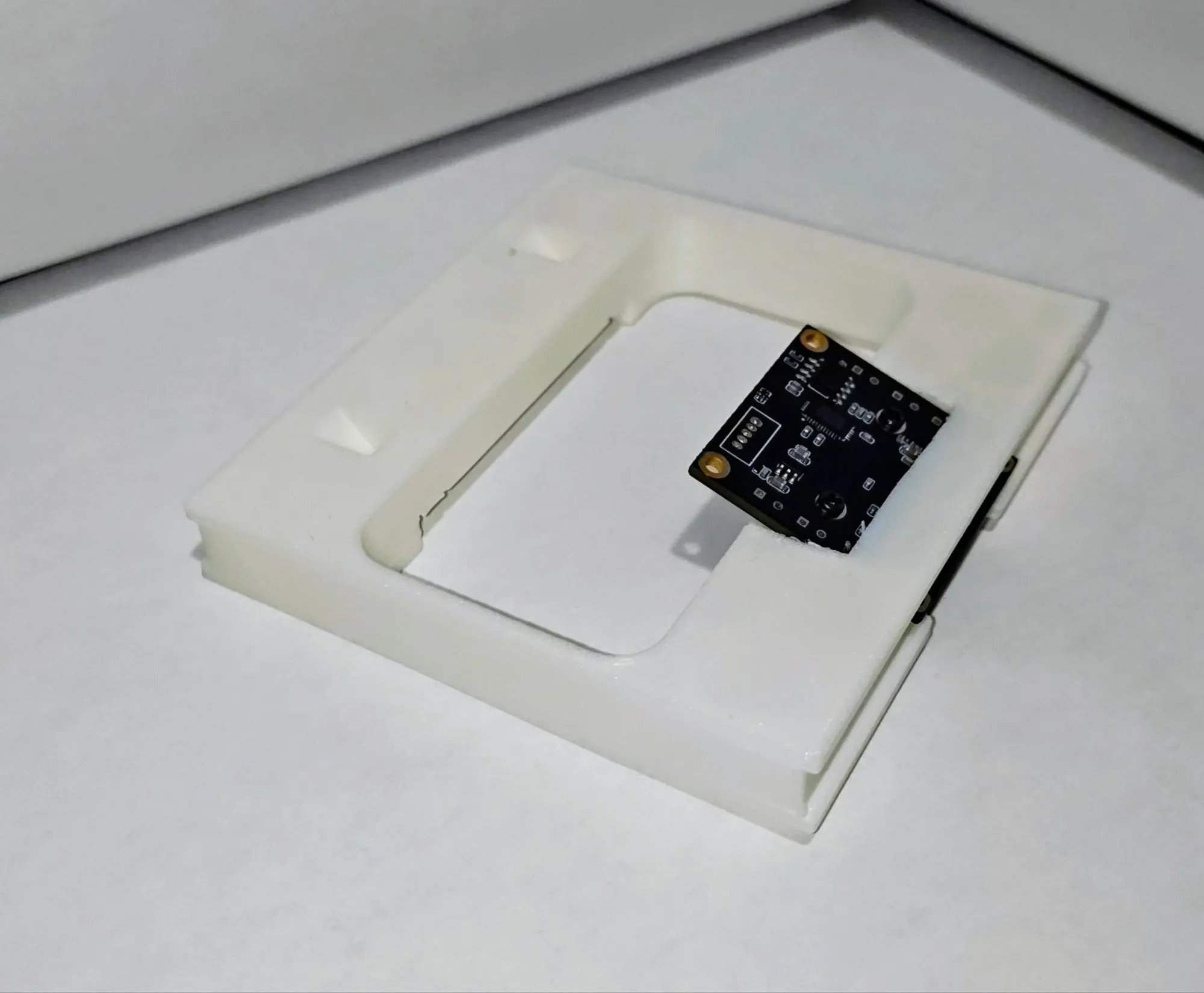
The brain is a Raspberry Pi Zero 2W, picked because we already had one and it supports the Pi camera directly. It runs a vision model that looks at the roots, decides if they’re dry, and runs the pump only when needed.
There are two pumps for two jobs. A 100 mL/min pump floods the channels fast during a drop test. A 1 mL/min pump handles slow watering for long-term growing, and it saves 320 mA, which matters when the whole budget is 500.
Sensors: a BME680 for temperature, humidity and air quality, and an Adafruit 4026 capacitive moisture sensor, picked over resistive probes because those corrode. A custom carrier board pulls the connections onto one board so there’s less loose wiring to fail.
Substrates, chosen on purpose
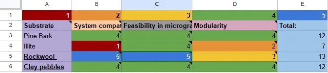
NASA asked for two substrates, so in December we scored four on system fit, likelihood of working in microgravity, and modularity.
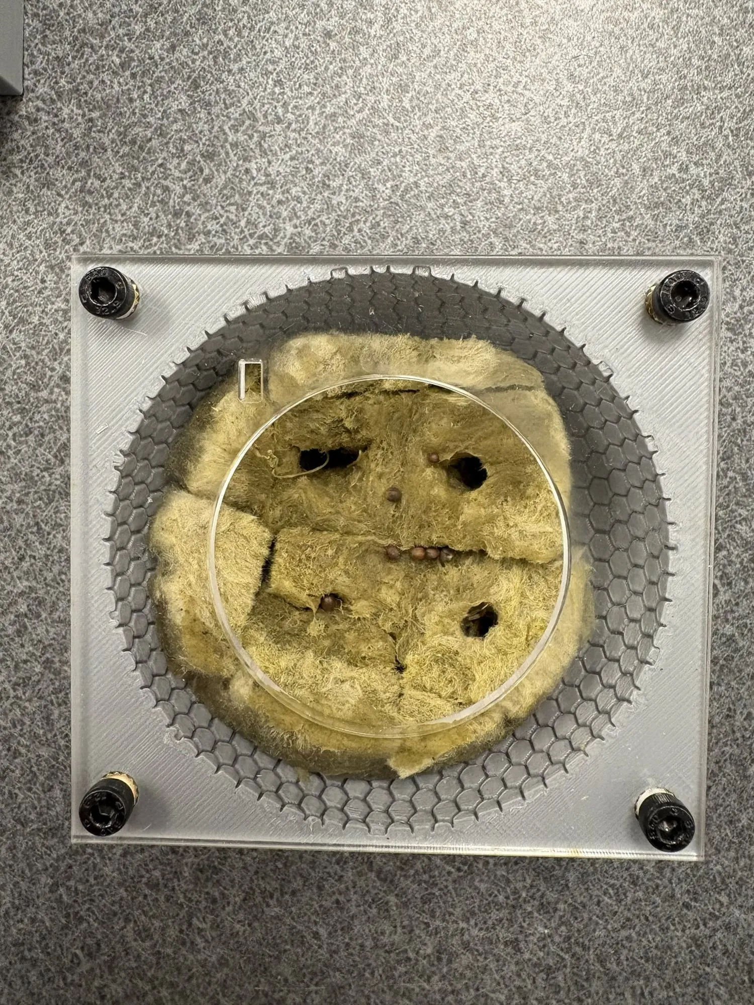
- Rockwool won with 13 points. It screws into existing holes, its binder doesn’t shed into the channels, and water moves through it well.
- Clay pebbles came second with 12, mostly because an 11.5 mm pebble can’t fall into a 0.48 mm channel.
- Pine bark was out because fragments would clog the channels. Illite clay was out because the fine powder would escape.
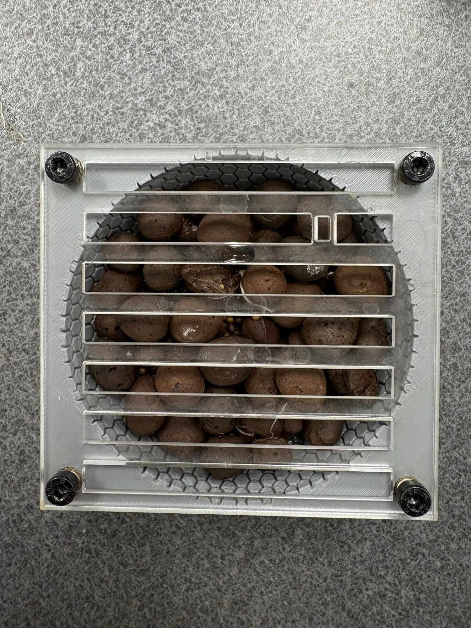
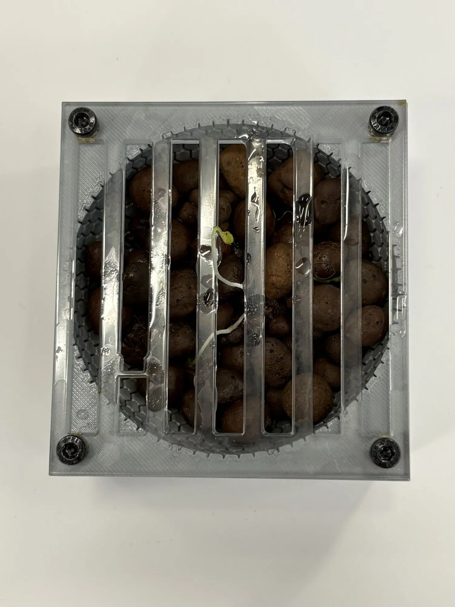
Testing
You can’t make microgravity in a school shop, so we didn’t pretend to. We built a ladder of tests. Each step could prove an assumption wrong, even though none could prove the design ready to fly.
- Flip it. We turned the module upside down and shook it with the substrate, covers and a planted stem in place. Nothing fell out. That shows the channels hold water against gravity. It says nothing about flow in free fall.
- Run water in. At 1 g, water climbed about halfway up the dome before gravity stopped it. That’s the baseline we expected to beat once gravity was gone.
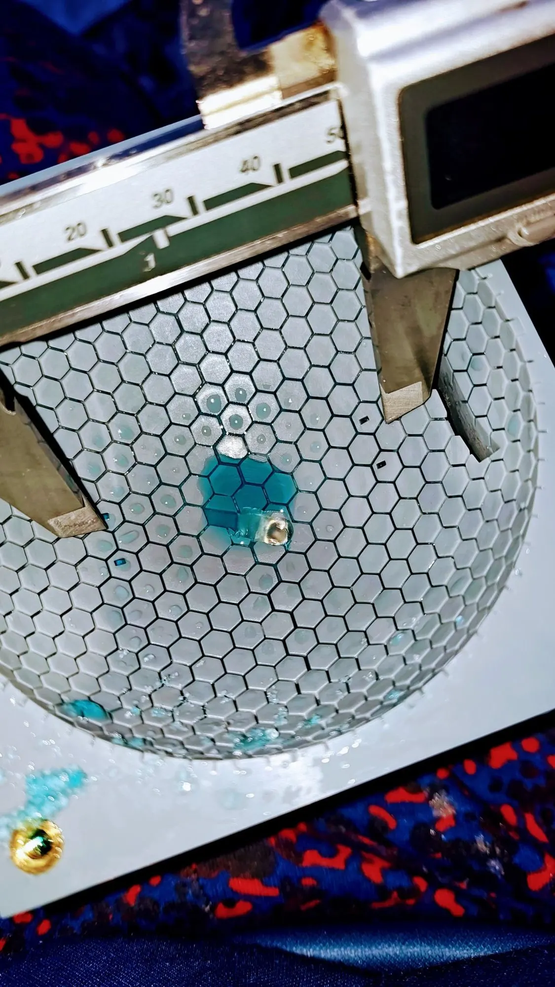
- Drop it. We dropped the sealed module from 14 feet, about 0.9 seconds of real free fall. Before each drop we added about 5 mL of dyed water to the center, then measured the spread with calipers. Compressed air cleared the channels between runs.
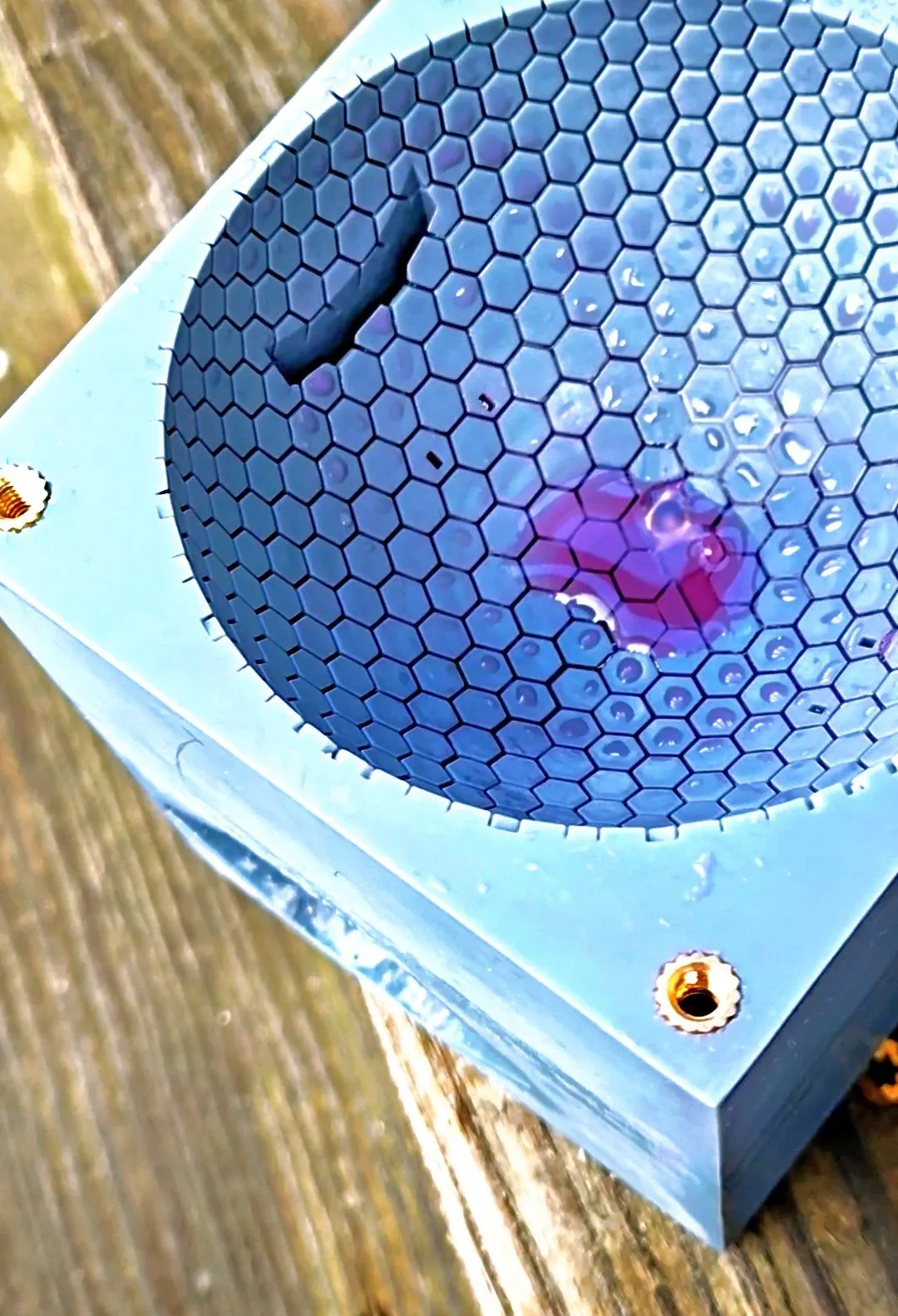
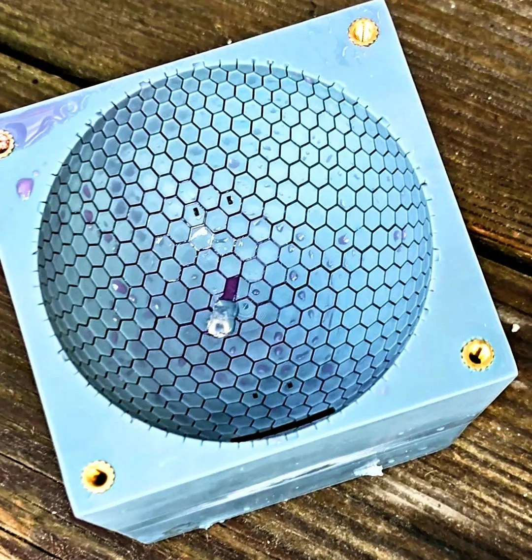
Testing also caught problems no screen would have shown:
- The plants kept dying. Our kale shriveled, and the cause turned out to be our own new resin printer running in the same unventilated room. We moved the plants, tented them, and added ventilation.
- A part three times too long. The pH probe we picked was 153 mm long, and we had 47 mm of room. We didn’t catch it until assembly, which is the expensive place to catch things.
Results
We ran two sets of 14 ft drops. The first six averaged about 9.9 mm of capillary movement. After we revised the module, the next nine averaged 14.7 mm, about a 48% improvement. The spread across those nine was wide, from 4.28 mm to 31.79 mm, which is what short, noisy free fall gives you.
Then the real one. On August 6, 2026, the nanolab went through NASA’s drop test: 2.21 seconds of free fall, more than twice what our drops could give us. Add where the test was and what the data showed

Until that test, every microgravity claim we made was an extrapolation from 0.9-second windows, and we said so on our site.
HexaFlow was named a NASA HUNCH finalist, and we’re presenting it at the ASGSR conference (American Society for Gravitational and Space Research) in December 2026.
What I learned
- Test the real thing. We tried to get a microgravity simulation running in software and couldn’t. A cheap 14 ft drop told us more than the sim did.
- Say what you don’t know. Being upfront that our drops were 0.9-second stand-ins made the real results more believable.
- Physical things fail in physical ways. A probe three times too long, a printer that poisons the plants. None of it shows up in CAD.
- Documentation is a deliverable. For a NASA review, if it isn’t written down with a drawing number, it didn’t happen. That’s also why the website mattered.
My role
My job was web development lead. The site is where reviewers, judges and anyone curious go to understand the project, so it had to explain capillary flow to people who’ve never heard of it.
I built it with Astro, Tailwind and Three.js: 16 pages covering the geometry, enclosure, electronics, substrates, drop tests, bill of materials and every CAD drawing.
The centerpiece is a 3D assembly viewer. You can spin the nanolab, click any part to isolate it, explode the assembly, switch to wireframe, toggle labels and hide fasteners. A list of 19 parts sits next to the model, and scrolling it lights up the matching part in 3D. Each part links to its drawing and CAD files, 37 native files in all (SolidWorks, KiCad and PDF).
Design choices and why:
- One data file is the source of truth for parts. The viewer links each mesh to its part by matching node names exported from SolidWorks. A teammate can fix a description without touching 3D code. The catch: renaming a part ID breaks the link, so that rule is written in the project docs, in bold.
- Clicking the model never scrolls the page. Originally, clicking a part scrolled the list to it, which yanked the page around while you were looking at the model. Now only scrolling the list moves the selection.
- Every runtime URL goes through one helper. The site lives in a subfolder on GitHub Pages. Astro fixes links it sees at build time, but URLs built in the browser (nav links, image paths, the 3D model file) 404’d. I wrote the helper plus a check that lists any URL that slips past it.
- Motion respects reduced-motion settings, and every number on the site was checked against the team’s design documents. If a document didn’t say it, the site doesn’t either.
The rest of the team: Aidan was project manager and hardware lead. Nate handled outside communication and water movement. Sabrina was note taker and substrate lead, and found the lizard. Maddie ran the schedule and led modularity. Everyone kept their own design notebook.
We also cold-emailed people who had done pieces of this before: researchers at the University of Arizona’s Mars-Lunar Greenhouse, a NASA capillary fluidics engineer, someone at Sierra Space, and MIT’s Space Exploration Initiative. Not everyone wrote back. The ones who did changed the design.
What’s next
The open items are the ones we listed at our last review: finish the custom PCB so it replaces the loose wiring, improve waterproofing, and do a long run with a live plant. Then ASGSR in December.
Add the drop test findings and anything that changed after ASGSRDemo video
Demo video coming soon: NASA drop test and dome flow test